Considerations For Flex Circuit Board Assembly
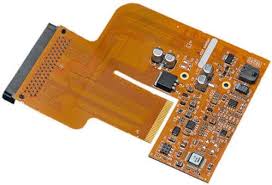
Flex Circuit Board Assembly
The considerations for flex circuit board assembly are more complex than rigid PCBs. In addition to the usual factors such as component placement, tracing and signal integrity, designers need to consider different bending radii for the flexible sections of the circuit board. It is also important to consider the environmental factors that a flex circuit may be exposed to including moisture, temperature variation and chemical exposure. This is why it is critical to choose the right materials and design the flex circuit board to withstand these conditions.
A flex circuit board is made of one or more conductive layers separated by flexible dielectrics. These layers are typically made from polyimide (PI) or polyethylene terephthalate (PET). Conductive material such as copper is used to create the circuit layout and patterns on the flex board. These are then etched away using light-sensitive materials such as photo-resist and stencils to expose only the areas that will become traces on the final product. Various adhesives can be used to bind the layers together. Thermoplastic adhesives like acrylic or urethane are often preferred as they can be reworked, while thermoset adhesives such as epoxy have better chemical resistance.
Once the circuit is etched, it is then cut to size. This can be done manually or with the help of a hydraulic punch and die set for large orders of rigid flex boards. For smaller orders a computerized system can be utilized that utilizes a library of cuts to make a specific sized flex circuit board. This method is faster but can lead to errors in the cutting process.
Considerations For Flex Circuit Board Assembly
As a general rule it is best to avoid hard right-angle bends in flex circuit track work. These can cause stress on the copper and can break the trace when flexing the board. Instead, it is recommended to route the traces with arc corner modes where possible. This helps spread the stresses over a larger area and reduces the likelihood of the copper tearing or cracking when the board is bent.
It is also a good idea to stagger traces between adjacent layer. This reduces the stress on a single layer when the flex circuit is bent and can help to prevent the copper from fatigue failure due to uneven stress distribution. It is also recommended that a minimum of 0.5 oz copper be used for external traces and 1 oz for internal traces. This will also improve reliability when the flex circuit is being bent dynamically.
Lastly, it is recommended to use cross-hatched patterns for ground planes on flex circuits as these provide more conductivity than solid copper areas. This can reduce impedance and reduce signal interference between the components on a flex circuit.
There are a number of other considerations when designing a flex circuit such as selecting the right material and stack up, ensuring proper bend radii and strain relief, and choosing the correct attachement methods for the assembly. These factors can affect the performance of a flex circuit and its longevity in service. By considering these factors during the design stage, a robust and reliable flex circuit can be created that will withstand repeated flexing and bending without failure.